Lab 5: Offline Robot Programming
Digital Twins & Offline Workflows with OCTOPUZ
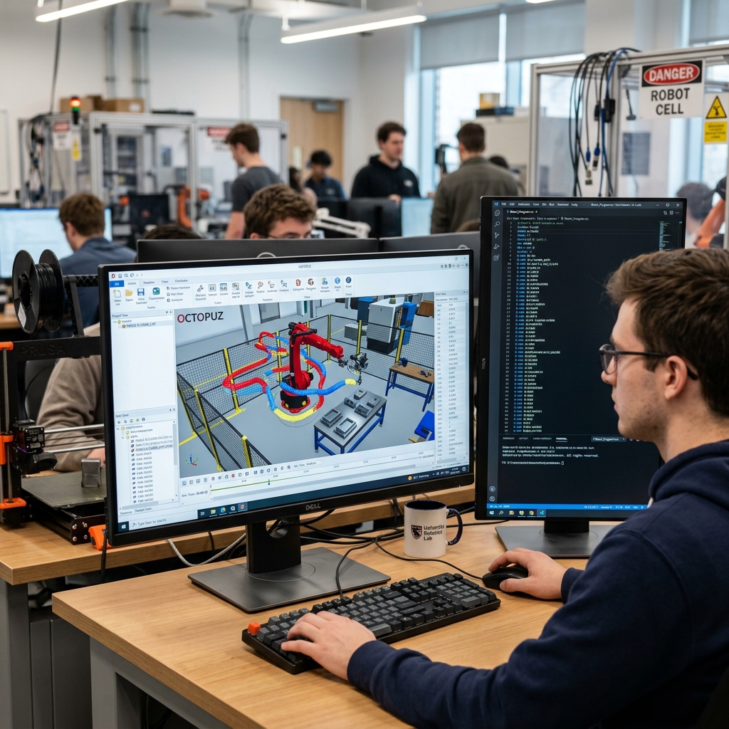
Master the art of simulating and programming industrial robots without touching the physical hardware. Program the UR5e and FANUC CR-7iA/L in a virtual cell.
OLP allows companies to program robots while production continues on the factory floor. It minimizes downtime, allows for complex path planning, and provides a safe environment for collision testing.
🎯 Learning Outcomes
What you will master in this session
OCTOPUZ Workflow
Load project files, navigate the workcell, and use the simulation environment to build robot programs.
Coordinate Frames
Understand World, Base, and Tool frames — the geometric foundation of all robot motion.
Multi-Robot OLP
Program a UR5e (6-axis) and a FANUC (7-axis with linear slider) for pick-and-place tasks.
📐 Robot Programming Basics
How robots "see" 3D space
Think about which coordinate system remains constant even if you move the robot's physical mounting position. (Hint: It's the one that "contains" the entire room).
📍 Tool Center Point (TCP)
The most critical point in robotics
The TCP defines the exact location that follows the programmed path.
Defining the TCP:
- Must account for the length of the gripper or tool.
- Must account for the weight (mass) and center of gravity.
- Incorrect TCP offsets lead to "collisions" in reality that don't show in simple sim.
🔍 Technical Insight
If the TCP is defined incorrectly in OCTOPUZ, the software will calculate correct motions for a wrong tool. This means every pick-and-place point will be shifted on the real robot.
🏗️ The Base Frame
The foundation of robot geometry
The Base Frame is the origin (0,0,0) for the robot's internal kinematics. Every move command you write is a set of coordinates offset from this point.
🔍 Pro Tip
The Base Frame is essential because it allows the software to transform 3D CAD paths into real joint positions. Every Downstream calculation (reach, collision) depends on it.
If the TCP is calculated incorrectly, will the robot's joint angles be wrong, or will its spatial accuracy be wrong? (Hint: The robot moves the TCP, not just its joints).
🚀 Motion Types: PTP vs. Linear
Choosing how the robot moves between points
Point-to-Point (PTP / MoveJ)
Each joint moves independently at its fastest speed. The path of the tool is unpredictable (curved).
Use for: Long moves in open, clear spaces.
Linear (MoveL)
The robot forces the TCP to follow a straight line between points.
Use for: Precise approaches, retracts, and picking parts.
🛠️ Setup & VLAB Access
Getting your workspace ready
1. VLAB Connection
- Use VM Horizon Client to log in.
- Search for "OCTOPUZ" in the start menu.
- Ensure you have a stable internet connection.
2. Project Files
- Download the Lab 5 CAD files and OCTOPUZ project.
- Open the `.octz` file to load the workcell.
- Verify both robots are visible.
⚠️ Preparation Check
This prep takes ~30 minutes. Do not wait until the lab session starts to install the software or download the files. Your lab time is for programming.
🔭 OCTOPUZ Interface
Your window into the digital twin
Viewport
The 3D space where you see the robot, fixtures, and parts. Left-click/drag to rotate.
Robot Tab
Tools for jogging the robot, setting the TCP, and checking joint limits.
Program Tree
The timeline of your program. This is where you add Move, Set, and Wait commands.
🤖 Part A: The UR5e Program
Automating a 11-step pick and place cycle
Repeat this logic for the Place position at the assembly fixture.
🛠️ UR5e Programming Details
Avoiding the common pitfalls
The "Wait" Command
Physical grippers take time to actuate. If you move the robot immediately after the Set DO command, the robot will lift before it has a grip on the part. Always add a 0.5s - 1.0s Wait.
Program Export
When done, you will export a .urp file. This file contains the script that the real UR5e controller reads.
🦾 Part B: The FANUC CR-7iA/L
Programming the yellow collaborative arm
The FANUC setup is slightly different. Instead of a gripper, you are using a Vacuum System to pick up acrylic coasters.
- Vacuum ON: Activates the suction.
- Vacuum OFF: Releases the part.
- Requires same Approach/Retract logic as the UR.
🔦 Note on Logic
FANUC programs are often exported as .LS files (readable text) and then converted to .TP (Teach Pendant) binary files for the robot.
⛓️ The 7th Axis (Linear Slider)
Extending the robot's work envelope
The FANUC robot in this lab is mounted on a track. This is your 7th degree of freedom.
Coordinate Check:
The 7th axis position is usually programmed as an External Axis value in your waypoint data. OCTOPUZ manages this automatically when you jog the slider.
💥 Collisions & Singularities
Visual warnings in the simulation
Red Overlay
Collision! The robot or tool has hit an object. You must adjust your waypoints.
Yellow Overlay
Singularity Risk! The robot's joints are aligning in a way that creates "infinite" speed requirements. Adjust orientation.
⏱️ Path Optimization
Saving time = Saving money
Once your program runs, look at the Cycle Time estimator in OCTOPUZ.
Reduce Cycle Time:
- Shorten the distance between waypoints.
- Switch PTP to Linear only where needed.
- Adjust the speed (%) of non-critical moves.
Keep it Safe:
- Don't compromise clearances for speed.
- Ensure "Home" is truly a safe parking spot.
📤 Exporting and Transfer
From the virtual world to the real robot
| Robot | File Format | Transfer Path |
|---|---|---|
| Universal Robots (UR) | .urp | USB Drive → Load Program on Teach Pendant |
| FANUC | .LS / .TP | Export .LS → Convert in ROBOGUIDE → Load .TP |
⚠️ TA Verification
You MUST have your simulation verified by a TA before you export the files for physical deployment. One small mistake in sim = a broken robot in reality.
🚨 Emergency & Safety
Review before entering the floor
Emergency Stop
Know exactly where the red E-Stop button is located for BOTH the UR and FANUC robots.
NUPD Emergency
Dial 3333 or 617-373-3333. Use the SafeZone app for immediate help.
🚫 Pro Tip: Stay Out
Never place any part of your body inside the robot's guard or work envelope while it is powered on. If you must enter, ensure the robot is in ESTOP or Manual/T1 mode with the deadman switch.
🚜 Physical Robot Deployment
The final test of your OLP work
✅ Lab 5 Summary
You are now an OLP Programmer!
Core Takeaways:
1. Think Geometry: TCP & Base are the foundation.
2. Linear for Precision: Always MoveL near the part.
3. Wait for Hardware: Don't rush I/O commands.
4. Simulation = Safety: Get a GREEN light in OCTOPUZ before reality.